th8320u1008 installation guide
TH8320U1008 Installation Guide: A Comprehensive Plan
This guide details installing the TH8320U thermostat, compatible with 24 Vac or 750 mV systems. Proper installation ensures efficient heating and cooling control, alongside safety precautions.

The Honeywell TH8320U is a touchscreen, programmable thermostat designed for versatile control of home comfort systems. It efficiently manages 24 Vac heating and cooling, or 750 mV heating setups, offering both battery power and common wire operation options. This universal thermostat provides electronic control, allowing users to select Heat-Off-Cool-Auto modes, with an ‘Em. Heat’ function specifically for heat pump systems.
Key features include selectable fan control – On, Auto, or Circulate – and adaptability to various system types. The TH8320U prioritizes user convenience and energy savings through programmable schedules and intuitive touchscreen navigation. Careful installation, following this guide, is crucial for optimal performance and longevity of the device.
Understanding System Compatibility
The TH8320U thermostat demonstrates broad compatibility, supporting both 24 Vac and 750 mV heating systems. 24 Vac systems are standard for many modern furnaces and air conditioners, while 750 mV systems are typically found in older millivolt heating setups. Determining your system’s voltage is the first step towards successful installation.
This thermostat also accommodates heat pump systems, featuring an ‘Emergency Heat’ (Em. Heat) configuration. It’s crucial to verify your existing wiring aligns with the TH8320U’s terminal requirements. Incorrect wiring can lead to system malfunction. The thermostat’s automatic or manual changeover capabilities further enhance its adaptability to diverse heating and cooling configurations.
Safety Precautions & Mercury Disposal
Prioritize safety during installation. Always disconnect power to your heating and cooling system at the breaker box before commencing any wiring work. Failure to do so presents a serious electrical shock hazard. Installation should be performed by a trained and experienced service technician to ensure adherence to safety standards.
If replacing an older thermostat containing mercury in a sealed tube, do not dispose of it with regular trash. Mercury is a hazardous material. Contact your local waste management authority for specific instructions on proper recycling and disposal procedures. Responsible mercury disposal protects the environment and public health. Follow all local regulations.
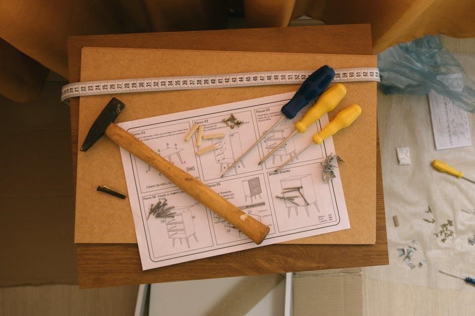
Tools and Materials Required
Before beginning the TH8320U1008 installation, gather the necessary tools and materials for a smooth process. You will need a small screwdriver (both flathead and Phillips head), wire strippers, and potentially a voltage tester to verify power is off. A level is crucial for ensuring the thermostat base is mounted straight.
Additional materials may include: pencil for marking screw locations, drill with appropriate bits if new mounting holes are needed, and wire labels for easy identification during wiring. Ensure you have fresh batteries if opting for battery power, or access to the common wire (C-wire) if utilizing that power source.
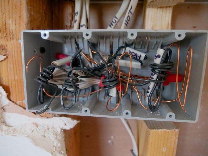
Step 1: Removing the Old Thermostat
Prior to installing the TH8320U1008, safely remove your existing thermostat. Begin by turning off power to your HVAC system at the breaker box to prevent electrical shock. Carefully remove the thermostat cover, exposing the wiring terminals. Important: Before disconnecting any wires, label each wire with its corresponding terminal designation using the provided wire labels or masking tape.
If your old thermostat contains mercury, handle it with extreme care and dispose of it properly according to local waste management regulations – do not discard it in regular trash. Once all wires are labeled, disconnect them from the old thermostat base. Gently remove the baseplate from the wall.
Step 2: Wiring the TH8320U1008
Connect the labeled wires to the corresponding terminals on the TH8320U1008 thermostat base. The thermostat supports both 24 Vac and 750 mV systems. Refer to the wiring diagram included with your thermostat for specific terminal designations. Ensure each wire is securely fastened to its terminal.
For 24 Vac systems, common terminals include Rh, Rc, W, Y, and G. For 750 mV systems, wiring will differ; consult the diagram. Double-check all connections against your labeling and the wiring diagram to avoid errors. Incorrect wiring can damage your HVAC system or the thermostat.
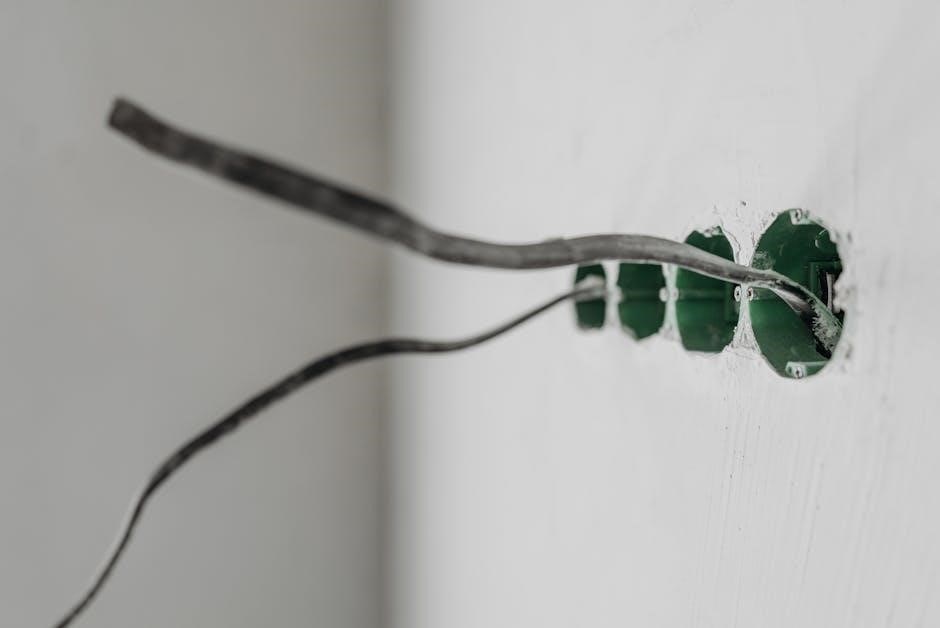
Identifying Terminal Connections
Before wiring, carefully identify each terminal on both your old thermostat and the TH8320U1008 base. Common terminals include Rh and Rc (24 Vac power), W (heating), Y (cooling), and G (fan). Note any existing jumper wires between Rh and Rc – these may need to be replicated on the new thermostat base.
For 750 mV systems, terminals will be different; consult the specific wiring diagram. Label each wire before disconnecting it from the old thermostat to avoid confusion. Accurate identification is crucial for correct operation and prevents potential damage to your HVAC system. A miswired connection can lead to malfunctions.
Connecting the Wires – 24 Vac Systems
With the power OFF at the breaker, connect the wires to the corresponding terminals on the TH8320U1008 base. Securely tighten each screw, ensuring a firm connection. Rh and Rc wires connect to the respective terminals; if a jumper existed on the old thermostat, replicate it here. Connect the W wire to the heating terminal, Y to cooling, and G to the fan.
Double-check all connections against your wiring labels and the system diagram. Loose wires can cause intermittent operation or system failure. Ensure no bare wire is exposed beyond the terminal. Proper 24 Vac wiring is essential for reliable thermostat function and HVAC system control.
Connecting the Wires – 750 mV Systems
For 750 mV systems, carefully identify the wires, as labeling conventions differ from 24 Vac setups. Typically, the ‘W’ wire connects to the heating terminal, but verify with your existing wiring diagram. Ensure the power is completely OFF at the breaker before proceeding with any connections.
Securely attach each wire to the designated terminal on the TH8320U1008 base, tightening the screws firmly. 750 mV systems require precise wiring for accurate temperature sensing and control; Double-check all connections to prevent operational issues and potential damage to the heating system.
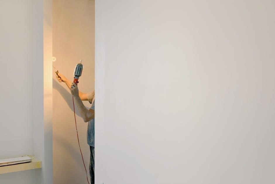
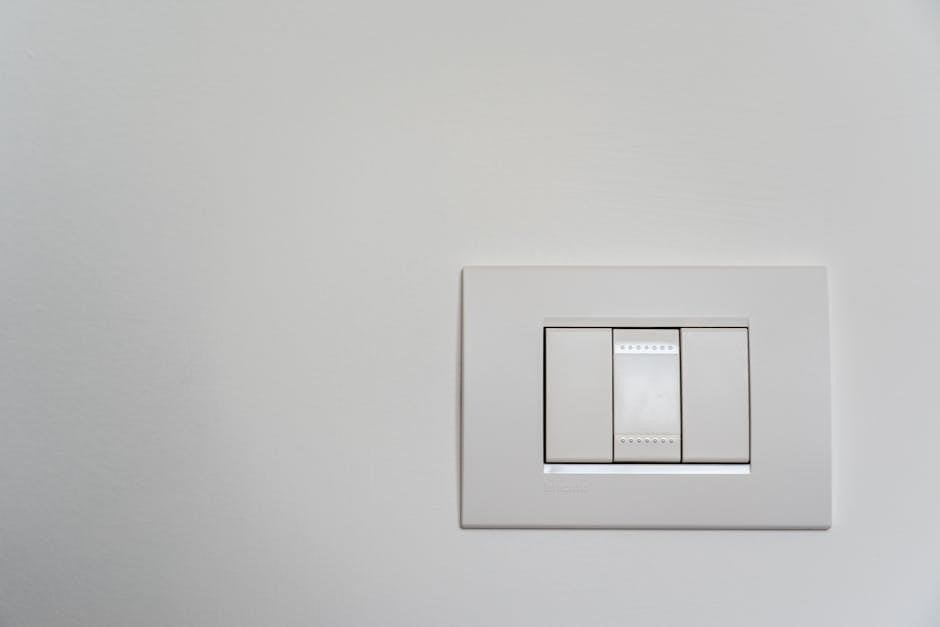
Step 3: Mounting the Thermostat Base
Securely mounting the thermostat base is crucial for stable operation. Select a location approximately 5 feet (1.5 meters) above the floor, ensuring good air circulation and avoiding direct sunlight or drafts. Avoid areas behind doors, in corners, or near supply vents.
Using the provided screws, attach the base plate to the wall. Ensure it’s level for proper display alignment. If mounting to drywall, use appropriate anchors for secure support. Verify the base is firmly attached before proceeding to the next step, preventing potential dislodging and wiring issues.
Selecting the Optimal Location
Choosing the right location significantly impacts thermostat accuracy and efficiency. Ideal placement is about 5 feet (1.5 meters) above the floor, on an interior wall with consistent temperature and good airflow.
Avoid areas prone to drafts – behind doors, in corners – or exposed to direct sunlight or heat sources like ducts. These conditions can provide inaccurate temperature readings, leading to inefficient heating or cooling. The location should represent the average temperature of the living space, ensuring comfortable and consistent climate control. Prioritize a representative spot for optimal performance.
Mounting the Base Plate
Before mounting, ensure the chosen location meets the optimal placement criteria – approximately 5 feet above the floor, away from drafts and direct sunlight. Use the base plate as a template, marking the screw holes on the wall with a pencil.
Drill pilot holes at the marked locations, using an appropriately sized drill bit for your wall material. Secure the base plate to the wall using the provided screws, ensuring it is level and firmly attached. A secure mounting is crucial for stable thermostat operation and prevents potential issues with wiring or display attachment. Double-check stability before proceeding.
Step 4: Attaching the Thermostat Display
Carefully align the thermostat display with the mounted base plate. Gently press the display onto the base, ensuring it clicks securely into place. Do not force the connection; misaligned pins could cause damage. Verify a snug fit from all angles, confirming the display is fully seated on the base plate.
Once attached, briefly inspect the display for proper alignment and stability. A secure connection is vital for reliable operation and prevents accidental disconnections. The touchscreen should respond smoothly to touch, indicating a successful attachment. Proceed to the next step only after confirming a firm and functional connection.
Step 5: Powering On and Initial Setup
Powering on the TH8320U can be achieved via battery installation or a common wire (24 Vac) connection. If using batteries, insert them according to the polarity markings within the battery compartment. With a common wire, the thermostat should power on automatically upon attachment. Observe the display for activation.
The initial configuration wizard will guide you through essential settings. This includes date, time, and system type selection. Carefully follow the on-screen prompts to accurately configure your thermostat. Correct system selection (heat pump or conventional) is crucial for proper operation. Save your settings to complete the initial setup process.
Battery Installation vs. Common Wire Power
The TH8320U offers flexible power options: batteries or a common wire (24 Vac). Battery power provides simplicity, ideal for installations lacking a common wire. However, batteries require periodic replacement, potentially interrupting thermostat operation. A common wire provides continuous power, eliminating battery concerns and ensuring consistent performance.
If a common wire is available, connecting it is highly recommended. This ensures reliable operation and unlocks all thermostat features. If using batteries, ensure they are fresh and correctly installed. The thermostat will display a low battery indicator when replacement is needed. Consider the long-term convenience when choosing a power source.
Initial Configuration Wizard
Upon powering on, the TH8320U initiates a user-friendly configuration wizard. This step-by-step process guides you through essential settings for optimal performance. The wizard begins by confirming the date and time, ensuring accurate scheduling. Next, it prompts you to select your heating and cooling system type – crucial for correct operation.
The wizard then asks about fuel source (gas, oil, electric) and system configuration (conventional or heat pump). Accurate selections are vital. Finally, it allows customization of fan control preferences. Following the wizard ensures the thermostat is tailored to your specific home and system, maximizing comfort and efficiency.
System Selection and Configuration
The TH8320U offers versatile system configuration options to match your home’s heating and cooling setup. Users can select from Heat-Off-Cool-Auto modes, providing flexible control over temperature. For heat pump systems, an ‘Em. Heat’ (Emergency Heat) configuration is available, activating auxiliary heat during extreme cold.
Proper system selection is critical for efficient operation. The thermostat automatically adjusts its behavior based on your choices. Incorrect settings can lead to discomfort or increased energy consumption. Carefully review your system type and consult a professional if unsure. The TH8320U adapts to various configurations, ensuring optimal performance.
Heat-Off-Cool-Auto Modes
The TH8320U thermostat provides four primary operating modes: Heat, Off, Cool, and Auto. In ‘Heat’ mode, the system prioritizes heating to maintain the set temperature. ‘Cool’ mode activates cooling when the temperature rises above the setpoint. Selecting ‘Off’ disables both heating and cooling.
‘Auto’ mode intelligently switches between heating and cooling to maintain the desired temperature, offering convenient, year-round comfort. The thermostat determines whether to activate heating or cooling based on the difference between the setpoint and the current room temperature. This mode is ideal for climates with fluctuating temperatures, optimizing energy efficiency and comfort.
Heat Pump (Em. Heat) Configuration

For heat pump systems, the TH8320U offers an ‘Em. Heat’ (Emergency Heat) configuration. This setting activates auxiliary or emergency heat when the heat pump cannot adequately warm the space, typically during extremely cold temperatures. Proper configuration ensures efficient operation and prevents excessive reliance on the more energy-intensive auxiliary heat.
The thermostat allows you to define the temperature at which ‘Em. Heat’ engages. Adjusting this setting optimizes the balance between comfort and energy savings. Incorrect settings can lead to unnecessary auxiliary heat usage or insufficient heating during cold snaps. Refer to your heat pump’s documentation for recommended ‘Em; Heat’ activation temperatures.
Fan Control Settings
The TH8320U thermostat provides versatile fan control options to optimize air circulation and comfort. Users can select from ‘On’, ‘Auto’, and ‘Circ’ modes. ‘On’ keeps the fan running continuously, providing consistent air mixing but potentially increasing energy consumption. ‘Auto’ operates the fan only during heating or cooling cycles, offering energy efficiency.
The ‘Circ’ (Circulate) mode runs the fan intermittently, even when heating or cooling isn’t active. This helps maintain even temperatures throughout the home and improves air quality by continuously circulating air. Selecting the appropriate fan setting depends on individual preferences and the home’s specific needs for air distribution and energy conservation.
On-Auto-Circ Options
Within the Fan Control settings, the TH8320U offers three distinct operational modes: On, Auto, and Circulate. Selecting ‘On’ ensures the fan operates continuously, regardless of heating or cooling demand, promoting consistent temperature distribution. ‘Auto’ mode activates the fan solely during active heating or cooling cycles, maximizing energy efficiency.
The ‘Circ’ or Circulate function intermittently runs the fan, even when the system isn’t actively heating or cooling. This gentle, periodic air movement helps prevent temperature stratification and enhances overall air quality. Choosing between these options allows homeowners to tailor the fan’s operation to their comfort preferences and energy-saving goals, optimizing the home environment.
Troubleshooting Common Issues
If the thermostat display is blank, verify battery installation or confirm a stable common wire connection. For inaccurate temperature readings, ensure the thermostat isn’t exposed to drafts, direct sunlight, or nearby heat sources. If the system doesn’t respond to commands, double-check all wiring connections at both the thermostat and the HVAC equipment.
Persistent issues may indicate a faulty thermostat or a problem within the heating/cooling system itself. Review the system compatibility section to confirm proper configuration. If problems persist after verifying these points, consult a qualified HVAC technician for further diagnosis and repair. Proper troubleshooting saves time and ensures optimal performance.
Technical Specifications & Ratings
The TH8320U thermostat operates on 24 Vac systems or 750 mV heating systems, offering versatile compatibility. Power options include battery operation or continuous power via a common wire (C-wire). It features automatic or manual changeover capabilities, supporting Heat-Off-Cool-Auto modes, with an Emergency Heat (Em. Heat) setting for heat pump systems.
Fan control options encompass On, Auto, and Circulate settings. The thermostat is designed for indoor use only, with a recommended mounting height of approximately 5 feet (1.5 meters) above the floor. Operating temperature range is typically 32°F to 104°F (0°C to 40°C). Refer to the full documentation for detailed electrical ratings and specifications.
Warranty Information
Honeywell International Inc. warrants this TH8320U thermostat against defects in materials and workmanship for a period of one (1) year from the date of purchase. This warranty applies to normal residential use and does not cover damage resulting from misuse, abuse, accident, alteration, or improper installation.
To obtain warranty service, contact Honeywell directly with proof of purchase. The warranty does not cover labor costs associated with replacement or repair. Honeywell’s liability is limited to the repair or replacement of the defective product, at Honeywell’s discretion. This warranty gives you specific legal rights, and you may have other rights which vary by location.
Resources and Support
For additional assistance with your TH8320U thermostat, Honeywell provides a wealth of online resources. Visit the official Honeywell Home website for frequently asked questions, detailed product manuals, and troubleshooting guides. You can also access helpful videos demonstrating installation and configuration procedures.
Technical support is available via phone or online chat. Contact information can be found on the Honeywell Home website or within the product documentation. Furthermore, Hydro-Temp offers drawing resources at http://www.hydro-temp.com/help/drawings/honeywell 69-1706.pdf for detailed diagrams and specifications.